

How Does a Collaborative Welding Robot Work?
A collaborative welding robot combines programmable robot motion with a controlled welding process. The robot moves a welding torch along a defined joint, while the welding power source controls current, voltage, wire feeding, and other process parameters.
Operators remain responsible for part loading, fixture inspection, program selection, welding procedure approval, first-piece inspection, and production monitoring.
A collaborative welding robot can improve consistency and reduce repetitive manual work. Stable results still depend on accurate parts, suitable fixtures, qualified welding parameters, correct torch access, and proper safety controls.
What Is a Collaborative Welding Robot?
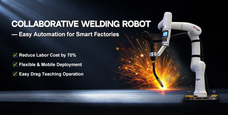
A collaborative welding robot is a robotic welding system designed for flexible programming and closer interaction with trained operators.
A complete system normally includes a six-axis robot arm, robot controller, welding torch, welding power source, wire feeder, cable package, workholding fixture, safety equipment, and optional seam-sensing devices.
The operator prepares the workpiece and selects the correct production program. The collaborative welding robot then performs the repetitive torch movement required by the welding procedure.
The term "collaborative" describes certain robot functions and operating modes. The term does not mean that arc radiation, welding fumes, sparks, electrical energy, hot metal, or moving equipment become harmless.
How Does a Collaborative Welding Robot Work Step by Step?
1. Analyze the Welding Requirement
A robotic welding project begins with the workpiece and the required weld quality.
The project team evaluates the material, thickness, joint type, weld position, weld length, allowable distortion, bead requirements, production volume, target cycle time, and inspection standard.
A qualified welding procedure or an approved parameter range should guide the setup. Robot repeatability cannot compensate for an unsuitable welding process.
2. Position the Workpiece in a Fixture
The operator places the workpiece in a fixture with repeatable locating surfaces and stable clamping points.
A collaborative welding robot normally follows stored coordinates. Changes in part location can move the joint away from the programmed torch path.
Fixture design should control the joint position while providing sufficient torch access. Fixture design should also support convenient loading, unloading, inspection, and maintenance.
3. Create or Select the Robot Program
A stored program can be selected for a repeat product. A new product requires a new or modified program.
Programming methods can include drag teaching, graphical programming, teach-pendant operation, coordinate entry, or offline programming.
The program normally records a home position, approach points, weld-start points, intermediate path points, weld-end points, and safe exit positions.
4. Verify the Torch Position
The operator checks the tool center point before production. Tool center point accuracy affects the relationship between the programmed robot position and the actual welding wire or torch location.
The operator also verifies torch angle, contact-tip-to-work distance, cable clearance, fixture clearance, robot posture, and access to every section of the joint.
5. Enter the Welding Parameters
The robot controller coordinates movement, while the welding power source controls the welding energy.
A welding program can include current, voltage, wire-feed speed, travel speed, gas pre-flow, gas post-flow, arc-start behavior, arc-end behavior, crater-fill settings, and weaving parameters.
Every parameter must match the material, thickness, filler wire, shielding gas, joint design, and required weld quality.
6. Perform a Dry Run
A dry run moves the collaborative welding robot through the programmed path without starting the welding arc.
The dry run helps identify insufficient reach, difficult robot postures, cable interference, fixture collisions, axis limits, singularities, and unsafe movement.
Any problem found during the dry run should be corrected before the first trial weld.
7. Complete and Inspect a Trial Weld
The first trial weld confirms whether the robot path and welding parameters work together correctly.
Inspection can include weld appearance, bead size, undercut, porosity, fusion, penetration evidence, distortion, spatter, and dimensional accuracy.
Production should begin only after the trial weld meets the applicable acceptance requirements.
How Is a Collaborative Welding Robot Programmed?
Drag teaching allows an operator to guide the robot toward the required positions and record welding points.
A graphical programming interface can reduce the amount of traditional robot code required for common welding tasks. Operators can arrange movement commands, welding commands, process settings, and control signals in a visual workflow.
Straight welds usually require fewer path points. Curved welds, circular joints, multi-segment products, and positioner-assisted welding require more detailed path planning.
Drag teaching simplifies position recording, but welding knowledge remains essential. The operator still needs to understand travel angle, work angle, heat input, shielding, bead placement, penetration, and defect prevention.
How Does Multi-Layer and Multi-Pass Welding Work?
Thick joints may require several weld layers and multiple passes.
A multi-layer and multi-pass program generates related welding paths using defined offsets. Different layers and passes can use separate positions, travel speeds, currents, voltages, and weaving settings.
The operator can inspect the generated path before welding and adjust individual layers when necessary.
Multi-pass automation does not remove the need for interpass cleaning, interpass-temperature control, distortion management, and weld inspection.
What Happens During a Typical Welding Cycle?
The operator loads the workpiece and confirms correct fixture location.
After receiving a ready signal, the collaborative welding robot moves from the home position to the approach point. The welding system starts shielding gas and activates the arc according to the programmed sequence.
The robot follows the defined path while maintaining the selected torch position, orientation, and travel speed. The program can change welding parameters, weaving behavior, or robot orientation at defined positions.
After completing the joint, the system stops the arc, performs the programmed post-flow sequence, moves away from the hot workpiece, and returns to a safe unloading position.
The operator then removes and inspects the welded part.
What Safety Measures Are Required?
Collaborative robot safety functions may include collision detection, speed monitoring, force monitoring, virtual boundaries, safety inputs, and controlled operating modes.
Welding introduces additional hazards beyond robot movement. Welding hazards include arc radiation, fumes, sparks, high temperatures, electrical energy, fire risk, sharp components, and hot workpieces.
A complete risk assessment should cover production, loading, teaching, program testing, consumable replacement, cleaning, maintenance, and troubleshooting.
The final installation may require welding screens, fume extraction, emergency stops, safety scanners, interlocked access, protective clothing, and fire-control measures.
A collaborative robot does not automatically make the complete welding cell fence-free. Safety requirements depend on the complete application and applicable local standards.
Which Applications Are Suitable?
A collaborative welding robot can be suitable for repeatable small- and medium-batch products.
Common applications include metal cabinets, machine frames, metal furniture, brackets, kitchen equipment, fitness equipment, agricultural components, construction machinery parts, automotive components, pipes, and general sheet-metal products.
Suitable applications normally have repeatable geometry, stable joint location, accessible welds, reliable fixtures, and clearly defined quality standards.
Applications with continuously changing parts, uncontrolled joint gaps, inaccessible welds, or extremely low production quantities may require additional engineering or a different production method.
What Are the Main Benefits?
A collaborative welding robot can provide more repeatable torch movement and travel speed across a production shift.
Automation can reduce repetitive operator fatigue and allow skilled welding personnel to focus on process development, difficult joints, quality inspection, and production improvement.
Stored programs can support faster product changeover when fixtures and program revisions are properly controlled.
Actual productivity should be measured using the complete production cycle rather than robot movement speed alone. Loading, clamping, tack welding, arc time, repositioning, cooling, unloading, inspection, rework, and changeover all influence the final output.
Conclusion
A collaborative welding robot works by combining programmable six-axis motion with a controlled welding process.
Drag teaching and graphical programming can simplify setup. Seam-location and tracking functions can compensate for defined levels of joint variation. Weaving and multi-pass functions can support more complex welding procedures.
Successful implementation still depends on part consistency, fixture design, qualified parameters, inspection, trained personnel, and application-specific safety engineering.
Evaluate a Huawei Laser Collaborative Welding Solution
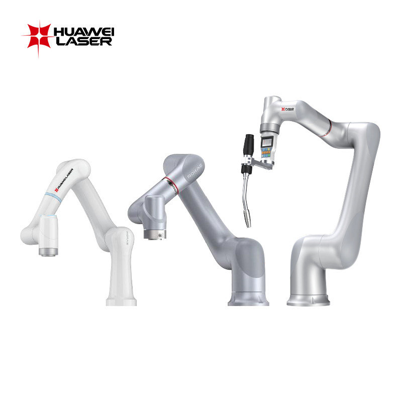
Huawei Laser provides collaborative welding robot configurations with payload options from 3kg to 12kg and working radii from 919mm to 1434mm.
Available configurations can provide six-axis movement, drag teaching, graphical programming, joint force sensing, collision detection, welding-process monitoring, weaving, multi-layer and multi-pass planning, and optional seam-location or seam-tracking functions.
Depending on the selected configuration, robot repeatability can range from +/-0.02mm to +/-0.05mm. Selected configurations can provide IP67 robot protection for demanding welding environments.
Specific payload, working radius, repeatability, protection rating, welding functions, sensors, welding power source, positioner, controller, and safety equipment must be confirmed according to the selected Huawei Laser solution.
Send Huawei Laser the workpiece drawing, material, thickness, joint type, weld length, production volume, current welding method, quality requirements, and target cycle time for a technical evaluation.