

How to Maintain the Correct Welding Torch Angle in Robotic Arc Welding
What Is Welding Torch Angle?
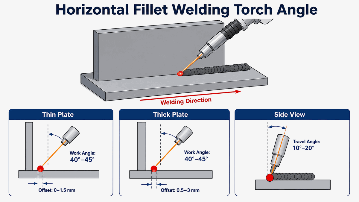
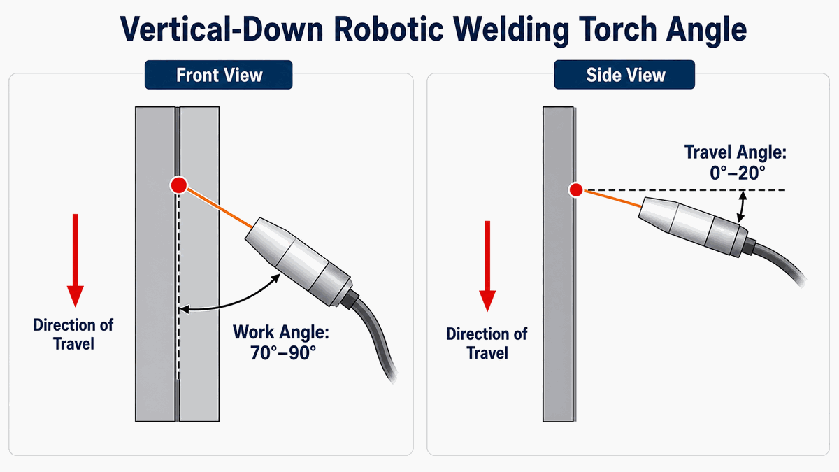
Welding torch angle normally includes two separate angles: work angle and travel angle.
Work angle describes the torch orientation relative to the surfaces forming the weld joint. Travel angle describes the torch inclination relative to the direction of movement.
Both angles affect where the arc force and welding heat are directed. A robot programmer should define and control both values rather than describing torch orientation with only one general angle.
What Is Work Angle?
Work angle is viewed across the welding joint.
For a symmetrical fillet weld joining two plates at approximately 90 degrees, an initial work angle near the joint bisector can help distribute heat between both members. The final angle may need adjustment when the plates have different thicknesses or heat-dissipation characteristics.
A thicker member can require more heat than a thinner member. A horizontal plate and a vertical plate can also respond differently because molten metal and gravity affect bead formation.
Groove welds usually require the torch to follow the groove centerline. Groove angle, root opening, land thickness, pass sequence, and desired sidewall fusion influence the final work angle. No single work angle is correct for every joint.
What Is Travel Angle?
Travel angle is viewed from the side of the welding direction.
A push angle points the torch in the direction of travel. A drag or pull angle points the torch back toward the completed weld.
For many GMAW applications, a moderate travel angle is used rather than holding the torch at an extreme inclination. A typical starting range is approximately 5 to 15 degrees, but the final value must follow the approved welding procedure and actual joint requirements.
An excessive travel angle can reduce shielding coverage, increase spatter, change penetration, and produce an irregular bead.
Push Angle or Pull Angle: Which Direction Is Better?
A push technique generally directs the arc ahead of the weld pool. A push orientation often produces a wider, flatter bead and can improve visibility of the joint.
A pull technique points the torch toward the weld pool. A pull orientation commonly produces a narrower bead with greater reinforcement and can increase penetration in suitable applications.
Push and pull results depend on the welding process, wire type, material, joint, transfer mode, parameters, and welding position. A general rule should never replace the welding procedure specification.
The robot program should use the direction qualified for the actual application.
Why Is Torch Angle More Difficult in Robotic Welding?
A manual welder can observe the weld pool and make continuous adjustments. A basic robotic welding system repeats the programmed position and orientation.
The robot can reproduce a correct angle very consistently. The robot can also reproduce an incorrect angle very consistently.
Torch orientation can change unexpectedly when a program passes through corners, circular joints, complex curves, positioner motion, or robot-axis singularities.
Programming only the start and end positions may allow the controller to interpolate an undesirable torch posture between points. Intermediate orientation points may be necessary to control the complete path.
Start With a Qualified Welding Procedure
Robot programming should begin with an approved welding procedure or verified process window.
The procedure should define the welding process, wire, shielding gas, current, voltage, travel speed, joint preparation, welding position, preheat requirements, and acceptance criteria.
The required work angle, travel angle, wire extension, and torch-to-work distance should also be documented when the values influence quality.
A program should not be approved only because the weld looks acceptable from one viewing angle. The trial weld must satisfy the applicable inspection requirements.
Calibrate the Tool Center Point
The tool center point represents the effective position of the welding wire or electrode relative to the robot flange.
An inaccurate tool center point creates errors when the robot changes torch orientation. A straight seam may appear acceptable, while a rotated or curved seam can move away from the joint.
TCP calibration should be checked after replacing the torch, neck, mounting bracket, anti-collision device, contact tip, or other components that can affect torch geometry.
A collision can bend a torch neck without producing an obvious external failure. A TCP verification should therefore be included after any suspected impact.
Control Contact-Tip-to-Work Distance
Contact-tip-to-work distance, commonly called CTWD, must remain stable along the welding path.
Changing CTWD can affect welding current, arc behavior, deposition rate, penetration, and gas coverage. CTWD variation can also make a correct torch angle produce inconsistent welds.
The robot path should maintain both torch orientation and distance from the joint.
A fixture error, worn contact tip, bent wire, incorrect TCP, seam-position change, or poorly programmed curve can cause CTWD variation.
Use Repeatable Fixtures
A robot follows programmed coordinates unless a sensing system applies a correction.
If the workpiece moves inside the fixture, the actual work angle and torch position relative to the joint also change.
Fixtures should provide repeatable locating surfaces, stable clamps, sufficient torch clearance, and controlled joint gaps.
Clamp position must be considered during path teaching. A torch angle that works on an unclamped sample may create a collision after all production clamps are installed.
Fixture wear should be checked regularly because worn datum points can gradually shift the joint.
Teach Position and Orientation Together
Every important robot point contains position and orientation information.
Recording only the wire location without checking torch posture can create acceptable endpoints but poor orientation between the endpoints.
The programmer should inspect the torch from several directions during teaching. A camera view or graphical interface can make orientation errors easier to identify.
Straight welds may require relatively few points. Curved seams and changing joint directions need enough points to maintain a smooth and controlled torch posture.
Unnecessary points should also be avoided. Too many poorly aligned points can create speed fluctuations and abrupt wrist movement.
Maintain the Angle Through Corners
Corners are common locations for torch-angle errors.
A robot approaching a corner must change direction while maintaining the required relationship between the torch and both joint surfaces.
The program may require an approach segment, corner-transition segment, and exit segment. Each segment should control orientation as well as position.
Travel speed and welding parameters may also require adjustment near a corner because heat accumulates differently than along a long straight seam.
A dry run should confirm wrist motion, cable clearance, fixture clearance, and the absence of sudden orientation changes.
Use a Positioner When Torch Access Is Limited
A positioner can rotate or tilt the workpiece so the robot can maintain a more favorable welding position.
Reorienting the workpiece can improve torch access, reduce extreme robot postures, and make the work angle easier to control.
A positioner can also help keep the weld pool in a stable relationship with gravity.
Coordinated robot and positioner motion requires accurate calibration. Positioner-axis errors can change torch angle and joint location even when the robot path is correct.
Consider Gravity in Vertical and Overhead Welding
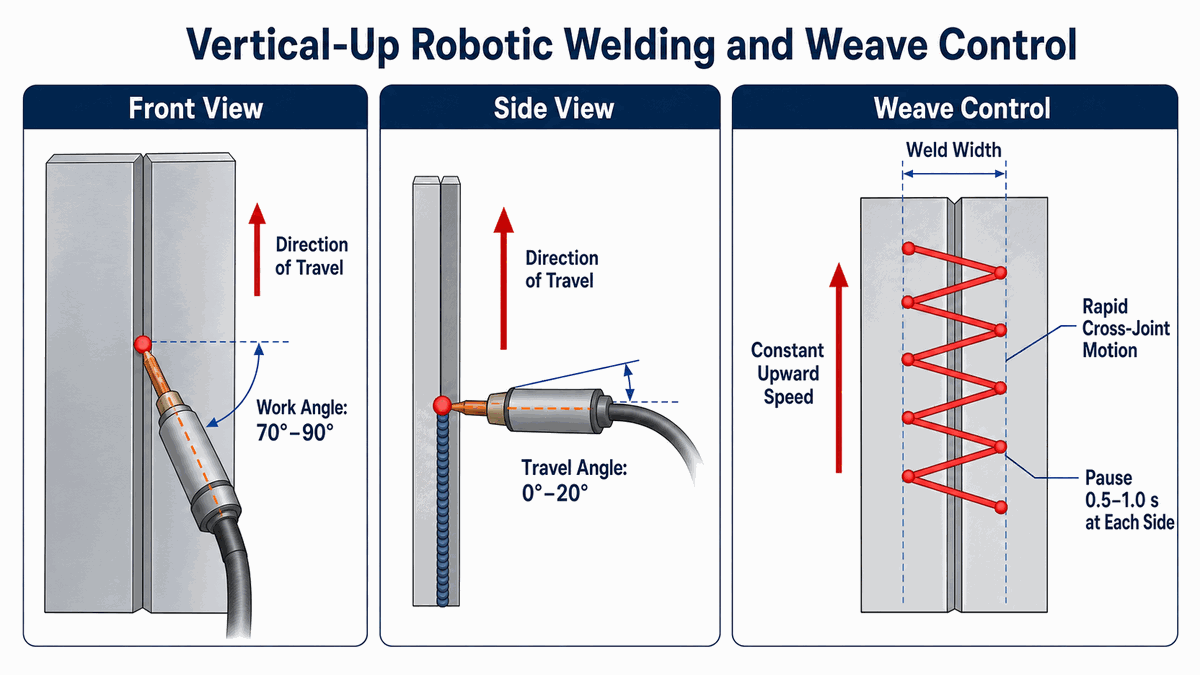
Gravity changes molten-pool behavior in vertical, horizontal, and overhead positions.
A torch angle that produces a stable bead in the flat position may not produce the same result in another position.
Vertical welding can require different travel speed, heat input, weaving, and torch orientation to prevent sagging, undercut, or poor fusion.
Overhead welding normally requires close control of heat input, arc length, joint preparation, and bead size.
Every welding position should be tested independently rather than copied from a flat-welding program without verification.
Check Torch Angle During Weaving
Weaving introduces side-to-side torch movement across the joint.
The robot should maintain the intended work and travel angles throughout the weave. Uncontrolled orientation changes can direct excessive heat toward one sidewall.
Weave width, frequency, dwell time, travel speed, current, and voltage all interact with torch angle.
A wide weave cannot automatically compensate for incorrect joint location or an unsuitable torch orientation.
Multi-layer and multi-pass programs should define the torch orientation for every layer because joint geometry changes as weld metal fills the groove.
Can Seam Tracking Correct Torch Angle?
Seam-location and seam-tracking systems can help compensate for defined levels of part variation.
Touch sensing or laser location can find the joint before welding and shift the programmed path.
Laser seam tracking can measure the joint during movement. Arc tracking can use welding-process feedback to apply path corrections in compatible applications.
Path correction does not always mean complete orientation correction. Some systems shift the robot path while preserving the programmed torch angle. More advanced configurations may adjust position and orientation.
Buyers should verify which correction dimensions are supported by the selected sensor, controller, software, and welding application.
Keep the Cable Package Under Control
Torch cables can influence robot movement and wrist orientation.
Incorrect cable routing can create pulling force, restrict joint motion, contact the workpiece, or interfere with fixtures.
Cable behavior should be checked across the complete robot program, including home movement, approach paths, welding paths, positioner motion, and maintenance positions.
Cable clamps should not create excessive stress near the torch neck or robot wrist. Consumable lines and cables should have enough movement allowance without creating uncontrolled loops.
Common Signs of an Incorrect Torch Angle
Unequal fillet-weld legs can indicate that the arc is directed too strongly toward one joint member.
Undercut on one side may result from an incorrect work angle, excessive travel speed, excessive voltage, poor weaving, or unsuitable heat distribution.
A high and narrow bead may be related to an excessive pull angle, low voltage, slow travel speed, or insufficient joint wetting.
A wide and flat bead with insufficient penetration may be associated with an excessive push angle, unsuitable parameters, or poor joint preparation.
Porosity can occur when an excessive angle reduces gas coverage, but porosity can also result from contamination, wind, leaks, an obstructed nozzle, incorrect gas flow, or excessive CTWD.
Torch angle should be investigated together with the complete welding process.
A Practical Torch-Angle Verification Procedure
Begin by confirming the workpiece revision, fixture, welding procedure, torch assembly, wire, shielding gas, and consumables.
Verify the TCP and confirm that the wire exits from the expected position. Check CTWD at the start, middle, and end of the weld.
Run the program without an arc. Observe the work angle and travel angle from multiple directions. Pay special attention to corners, curves, approach movements, and positioner transitions.
Complete a trial weld using representative production parts. Inspect bead position, fillet-leg equality, penetration evidence, undercut, fusion, spatter, porosity, and distortion.
Save the approved program with a controlled revision number. Record any required fixture, torch, TCP, parameter, or inspection conditions.
How Often Should Torch Angle Be Checked?
Torch angle should be verified during initial setup and after any change that can affect the relationship between the torch and workpiece.
Relevant changes include torch replacement, contact-tip replacement, torch-neck adjustment, collision, fixture repair, product revision, program modification, robot relocation, positioner calibration, and seam-sensor adjustment.
Production teams should also monitor gradual changes. Consumable wear, cable movement, loose mounting hardware, fixture wear, and thermal effects can create small deviations over time.
Inspection frequency should reflect production volume, weld criticality, process capability, and customer requirements.
Safety During Robot Teaching and Welding
Torch-angle adjustment can place personnel close to the robot, fixture, welding torch, or workpiece.
A task-based risk assessment should cover teaching, dry runs, inspection, troubleshooting, consumable replacement, maintenance, and automatic production.
Robot safety functions do not eliminate welding hazards. Arc welding can expose personnel to fumes, ultraviolet radiation, burns, electrical hazards, sparks, hot surfaces, and moving machinery.
The installation may require welding screens, local exhaust ventilation, interlocked access, safety scanners, emergency stops, protective clothing, and controlled operating modes.
Conclusion
Maintaining the correct welding torch angle requires coordinated control of work angle, travel angle, TCP, CTWD, fixtures, robot orientation, welding parameters, and part consistency.
A robot can maintain the required torch posture with high repeatability after the path has been properly developed and verified.
Routine calibration, dry-run inspection, representative trial welding, and controlled program revisions help prevent gradual changes from becoming production defects.
Evaluate a Huawei Laser Robotic Welding Solution
Huawei Laser provides robotic welding solutions with drag teaching, graphical programming, six-axis motion, welding-process control, weaving, multi-layer and multi-pass planning, and optional seam-location or seam-tracking functions.
Huawei Laser can evaluate torch access, robot reach, payload, fixture design, positioner requirements, welding parameters, sensing options, and safety equipment according to the customer's actual workpiece.
Send Huawei Laser the workpiece drawing, material, thickness, joint type, welding position, weld length, production volume, quality requirements, and target cycle time to request a technical evaluation or sample welding test.