
The Ultimate Guide to Complex Bevel Cutting with a Tube Laser Cutting Machine
Complex bevel cutting transforms a tube laser cutting machine from a standard profiling system into an integrated cutting and weld-preparation solution. A bevel-capable machine can produce angled edges, mitered ends, saddle joints, countersunk holes, and compound contours during one cutting cycle.
Integrated bevel cutting can reduce manual grinding, milling, handling, and secondary preparation. Reliable results, however, depend on suitable joint design, accurate programming, stable material support, collision avoidance, and careful process validation.
What Is Complex Tube Laser Bevel Cutting?
Conventional tube cutting directs the laser beam approximately perpendicular to the local material surface. Bevel cutting tilts the cutting head so the beam enters the tube at a programmed angle.
A bevel-capable tube laser cutting machine coordinates tube rotation, longitudinal movement, cutting-head positioning, and head inclination. Coordinated motion allows the system to process changing angles around round, square, rectangular, and other supported profiles.
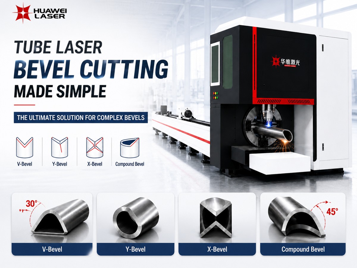
Typical geometries include V, Y, X, and K weld preparations, angled tube ends, saddle connections, and bevels that change direction along a three-dimensional contour. The available angle and geometry range depends on the machine, profile, wall thickness, cutting-head travel, and application.
Why Use a Tube Laser Cutting Machine for Beveling?
Traditional tube processing may require laser cutting followed by manual grinding, sawing, milling, or separate weld-edge preparation. Every additional operation increases handling time and introduces another opportunity for dimensional variation.
A tube laser cutting machine can combine profiling and edge preparation in one programmed process. Integrated processing can shorten production flow, reduce work in progress, and improve consistency between components.
Accurate bevels can also simplify fitting and welding. When bevel angle, root face, and mating contour remain consistent, welders can maintain a more repeatable joint opening and spend less time correcting parts manually.
Laser-cut tabs, slots, and locating features can further improve assembly efficiency. A suitable tubular design may reduce fixture requirements and eliminate several downstream preparation steps.
Why Is Complex Bevel Cutting Difficult?
An angled laser cut passes through a longer effective material path than a perpendicular cut. As the angle increases, the required cutting conditions and molten-material flow can change.
The upper and lower edges of a bevel also follow different geometric paths. Software must compensate for the bevel angle, root-face height, kerf width, local surface direction, and required finished dimensions.
Curved tubes create continuously changing surface positions. Square and rectangular profiles introduce rapid transitions around corner radii. The cutting head must follow each transition while maintaining focus, stand-off distance, and sufficient nozzle clearance.
Production tubes can also contain straightness error, twist, ovality, wall-thickness variation, and changing corner radii. Process validation should therefore use several representative tubes rather than one ideal sample.
Begin with the Joint Design
A successful bevel begins with a manufacturable drawing. The drawing should clearly define the bevel angle, root face, joint opening, reference surface, dimensional tolerance, and welding purpose.
The selected angle should come from the joint design and welding procedure rather than the maximum tilt of the cutting head. Larger angles increase the effective cutting thickness and may require different speed, focus, piercing, and gas settings.
Root-face consistency is equally important. An excessive root face may make penetration more difficult, while an insufficient or irregular root face may increase burn-through risk and change filler-metal demand.
Designers should also confirm that the nozzle and cutting-head body can physically reach the requested contour. A valid CAD model does not automatically guarantee collision-free machining.
Programming, Kerf Compensation, and Collision Avoidance
Kerf compensation for a vertical cut is relatively simple. Bevel cutting requires compensation in three-dimensional space because the top and bottom edges are offset from one another.
Programming software must calculate the local tube surface, cutting-head vector, kerf position, bevel angle, and coordinated axis movement. Simple two-dimensional offsets are rarely sufficient for changing-angle contours.
Collision risk increases when the cutting head tilts toward the tube, chuck, support, or a previously cut feature. Corners, deep bevels, intersecting contours, and open profiles can create restricted spaces.
Collision simulation should use a digital cutting-head model that matches the physical machine configuration. Simulation should be repeated after toolpath changes because passing a two-dimensional contour check does not confirm three-dimensional clearance for a tilted head.
Focus, Cutting Parameters, and Heat Control
Stable focus and nozzle stand-off are essential for consistent bevel quality. When the cutting head tilts, physical clearance changes and surface following becomes more demanding.
A parameter developed for a perpendicular cut should not automatically be applied to every bevel. Laser power, cutting speed, gas pressure, focus position, nozzle type, stand-off distance, and piercing conditions may require adjustment.
Piercing and lead-in positions should be placed away from critical finished surfaces whenever possible. A poorly positioned pierce can leave a visible mark or produce local roughness on an important welding edge.
Cutting sequence also affects quality. Closely spaced contours may concentrate heat and distort thin-walled tubing. A suitable sequence distributes heat and preserves tube stiffness until critical features are complete.
Clamping and Material Support
Tube movement directly affects feature position and bevel accuracy. The chuck must center and hold the tube without introducing excessive deformation.
Long or heavy tubes require appropriate supports to control sagging and vibration. Poor support changes the actual surface position even when the programmed trajectory is correct.
The remaining tube skeleton may lose stiffness as holes and profiles are cut. Cutting order should prevent the workpiece from moving before important bevels are completed.
Clamping, support, and unloading should be tested with the actual profile size and weight. A setup that works for a short, light tube may not remain stable with a longer production part.
Inspection and Common Quality Problems
Visual inspection can identify excessive dross, incomplete cutting, surface damage, and obvious angle variation. Visual appearance alone cannot confirm every critical dimension.
An inspection plan should consider bevel angle, root-face height, contour position, hole location, tube-end length, corner quality, and mating fit. Sectioned samples are particularly valuable during process development because the cross-section reveals the actual kerf profile and root geometry.
Excessive dross may result from unsuitable speed, focus, gas settings, nozzle condition, or material variation. An inconsistent bevel angle may indicate axis-calibration error, tube movement, inaccurate profile data, or unsuitable geometric compensation.
An irregular root face may result from unstable height following, incorrect kerf compensation, or changing tube position. Poor corner quality can be caused by abrupt axis movement, unsuitable speed control, rapid surface transitions, or insufficient nozzle clearance.
A collision or near-collision normally indicates a problem with toolpath design, machine configuration, simulation, or the cutting-head model. Production should stop until the cause has been identified and corrected.
A Practical Validation Process
Begin by reviewing the drawing and confirming that every requested contour is accessible. Check axis travel, cutting-head angle, nozzle clearance, chuck position, and support locations.
Simulate the complete program with the correct cutting-head model. Run the first physical test under controlled conditions and monitor restricted areas closely.
Measure bevel angle, root-face height, contour position, and mating fit. Inspect straight sections, corners, starts, stops, and changing-angle transitions.
Repeat the test with several tubes from the intended production batch. A process should be released only after repeatability has been demonstrated under realistic loading, cutting, and unloading conditions.
Structural and safety-critical components may also require process qualification, mechanical testing, or nondestructive inspection according to applicable standards.
Choosing a Bevel-Capable Tube Laser Cutting Machine
Machine selection should consider profile diameter, cross-section, tube length, wall thickness, part weight, required bevel range, and production volume.
Buyers should evaluate cutting-head accessibility, chuck and support design, three-dimensional collision simulation, complex-contour programming, parameter management, nesting capability, calibration procedures, operator training, and technical support.
A machine trial should use actual drawings and representative material. The test should include changing angles, corner transitions, intersecting contours, and required welding fit rather than only a simple straight bevel.
The business case should be calculated across the complete production route. A bevel contour may take longer to cut, but total manufacturing time can fall when grinding, handling, fitting, and rework are reduced.
Conclusion
Complex bevel cutting allows a tube laser cutting machine to combine profiling and weld preparation in one production cycle. Potential benefits include fewer secondary operations, more consistent joint geometry, faster assembly, and improved process traceability.
Reliable production depends on suitable joint design, accurate tube data, three-dimensional compensation, stable clamping, controlled cutting parameters, collision avoidance, and representative testing.
The best result is not simply an angled edge. The best result is a repeatable tube component that fits correctly, supports efficient welding, and passes inspection with less downstream preparation.
Explore Huawei Laser Tube Cutting Solutions
Huawei Laser provides tube laser cutting solutions for manufacturers producing tubular structures, welded frames, machinery parts, furniture components, and customized metal assemblies.
Explore Huawei Laser tube laser cutting machine or contact Huawei Laser to discuss tube dimensions, bevel requirements, production drawings, automation needs, and sample-cutting evaluation.