

How to Choose the Right Laser Welding Wire Diameter
Choosing the correct laser welding wire diameter helps improve gap filling, bead appearance, feeding stability, and production consistency. Wire that is too thin may not supply enough filler metal. Wire that is too thick may be difficult to melt completely and can make process control more demanding.
Laser welding wire diameter should not be selected from sheet thickness alone. A reliable decision also considers filler alloy, joint design, fit-up variation, laser power, travel speed, wobble settings, wire feed speed, and feeder compatibility. No single diameter chart applies to every application, so production-representative trials remain essential.
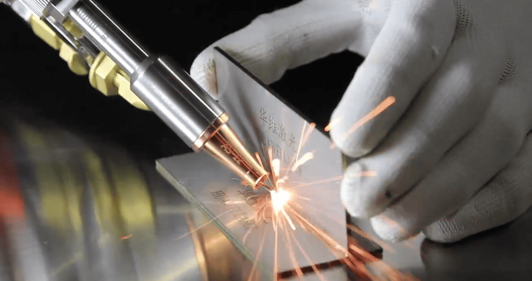
Why Is Filler Wire Used in Laser Welding?
Autogenous laser welding forms a joint by melting the base material without added filler. The method can work well when parts have accurate edges, small gaps, and repeatable clamping. Adding wire supplies extra metal to the weld pool, helping fill a controlled joint gap and shape the finished bead.
Filler wire cannot replace sound fit-up. Large gap variation, excessive mismatch, contamination, or unstable clamping can still produce inconsistent fusion. Selection of laser welding wire diameter should begin only after the parts, joint surfaces, and fixture can deliver a repeatable welding condition.
What Does Wire Diameter Affect?
Wire diameter affects the volume of metal delivered per unit length, the required feed speed, melting response, weld-pool behavior, and bead reinforcement. Changing diameter alters filler-metal mass flow even when the displayed wire feed speed remains unchanged.
Wire diameter also affects feeding behavior. Fine wire bends more easily and can be sensitive to liner friction, tight bends, and incorrect drive-roll pressure. Coarser wire has greater column strength, but the wire requires compatible consumables and enough energy for stable melting.
Start With the Actual Joint Gap
Joint gap is one of the most important inputs when selecting laser welding wire diameter. A small and consistent gap may be easier to control with fine wire. A joint requiring more filler can justify evaluating a larger diameter, provided the laser process can melt the increased metal flow reliably.
Measurements should cover more than one ideal sample. Record minimum, average, and maximum gaps across multiple parts, and check whether the gap changes along the seam. The selected process should tolerate normal manufacturing variation without relying on excessive filler metal.
Match Wire Diameter to Weld Size
Butt joints, lap joints, and fillet joints require different filler volumes. A small fillet or a weld with strict cosmetic requirements may benefit from an initial trial with finer wire. A larger weld cross-section can make a coarser wire more practical, but only when complete fusion is maintained.
Surface width alone is not sufficient evidence of weld quality. A bead can appear full while root or sidewall fusion remains incomplete. Cross-section testing, mechanical testing, or an appropriate nondestructive method should confirm the result.
Consider Base-Material Thickness
Material thickness influences heat capacity, penetration requirements, and the available heat-input window. Material thickness is important, but thickness does not determine laser welding wire diameter by itself. Identical sheet thicknesses can require different wire settings when joint type, gap, speed, or required bead size changes.
Thin-sheet work often emphasizes distortion control, burn-through prevention, and surface appearance. Thicker parts may place greater emphasis on fusion, deposition volume, and cycle time. Estimate the filler volume required by the joint before selecting a wire that the equipment can melt consistently.
|
Plate Thickness |
Recommended Wire Diameter |
|
0.5–1.5 mm |
0.8 mm wire |
|
1.5–3.0 mm |
1.0 mm wire |
|
3.0–4.5 mm |
1.2 mm or 1.6 mm wire |
|
≥ 3 mm (high filler demand) |
Optional dual-wire feeder (e.g., dual 1.0 mm wires) |
Check the Feeder's Supported Diameter Range
Before ordering wire, verify the supported range of the wire feeder, drive rolls, liner, feeding hose, and contact or guide tip. A feeder may support a stated diameter while the consumables currently installed are intended for another size.
Diameters such as 0.8, 1.0, 1.2, and 1.6 mm are found in some handheld laser welding wire-feeding systems. The available range depends on the actual configuration, and common sizes must not be treated as a universal recommendation. Follow the equipment and welding-head specifications.
Match Drive Rolls, Liners, and Tips
Drive-roll groove shape and pressure directly affect feeding stability. Insufficient pressure can cause slipping. Excessive pressure may deform the wire, create debris, or increase resistance. After changing laser welding wire diameter, inspect the drive-roll groove, liner size, and guide-tip clearance.
Keep the wire path smooth and avoid tight hose bends. Excessive hose length, abrupt curves, and internal contamination can amplify speed variation. Stable mechanical feeding is a prerequisite for meaningful welding-parameter development.
How Does Diameter Influence Melting?
At the same linear feed speed, a larger wire delivers more metal into the weld pool and requires more energy for heating and melting. Insufficient energy can cause the wire to push against the workpiece or pool, produce unmelted material, or interrupt the bead.
Fine wire generally responds more quickly to heat, but a higher wire feed speed may be required to achieve the same deposition volume. Very high feed speed can make the process harder to control and may increase feeding vibration or weld-pool disturbance.
Common Laser Welding Wire Diameters
A range of approximately 0.8 to 1.6 mm is common in some handheld laser welding systems. Fine sizes may suit low filler demand and detailed appearance control. Larger sizes may support higher filler demand when sufficient melting capacity is available.
Common availability does not equal application approval. Final laser welding wire diameter must reflect the alloy, joint design, measured gap distribution, equipment configuration, target speed, and acceptance criteria.
A Practical Selection Procedure
First, document the base-metal grade, thickness, joint type, and acceptance criteria. Second, measure gap and mismatch across several production parts. Third, verify the supported wire sizes and installed feeder consumables. Fourth, choose a conservative starting diameter and establish an initial parameter window. Fifth, weld representative parts in the real fixture, orientation, and target cycle time. Finally, verify appearance and internal quality through cross-sections, mechanical testing, or suitable nondestructive inspection, then record the approved process.
Conclusion
The right laser welding wire diameter results from joint requirements, equipment capability, and verified trials. Control fit-up first, confirm feeder compatibility, and then develop a stable window that balances diameter, wire feed speed, laser energy, travel speed, wobble, and wire position.
Avoid treating material thickness or a commonly stocked size as the only selection rule. Repeated trials with representative parts and suitable quality checks are necessary to convert an initial setting into a stable, traceable production process.